Radio Range Approach Plates
Explained
By Allan Greene
Well, by virtue of the fact that you’re reading this, I’ve got to assume that you’re interested in learning more about how to properly interpret the recently-released approach plates. These plates stemmed from the DC-3 Airways Radio Range project conducted principally by Dave Bitzer, Norman Hancock, Alex Nicolson, Doug Dawson and Michael Ostrow (and I hope I didn’t leave anyone out.) I saw the need – well, my need anyhow – for relatively simple and easy to interpret Instrument Approach Procedures (from now on I’ll refer to them as IAPs or Approach Plates or Approach Charts) for which a Flight Simulator pilot would be able to fly approaches via “the Beam” with nothing other than a pair of ears and an ADF receiver (and, of course, the aforementioned Radio Range project – properly installed). Since this was a DC-3 Airways project, any techniques mentioned will usually reference flight in a DC-3 aircraft. If you’re using another aircraft you will have to modify the procedures to fit whichever bird you’re flying. Generally speaking though, the techniques presented should adapt well to most any piston-powered airplane out there.
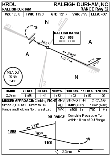
If you haven’t seen the results yet, here is a pretty typical IAP:
Essentially, these IAPs are broken down into four sections: General Data, Plan View, Approach Data, and Profile View and share similarities to both Jeppesen and US Government issue real-world IAPs. There is much more information that could have been added, but I felt that with these plates, the Flight Simulator pilot can safely fly approaches into any of the designated airports. There are many more airports that could have had approaches designed off of the same Ranges, but time constraints dictated that I limit the airports served to only one per Radio Range. So, let’s get to the nitty-gritty.
Here, the pilot will find Identifying Information as well as some communications and geographical data about the IAP.
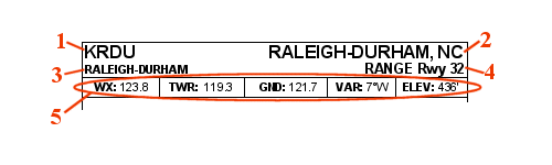
Figure 2.
§ It seems self-evident that a Range Station is the only navigational facility used in this approach. The Northwest Leg of the Raleigh Range goes directly over the airport. That’s just what an approach designer wants. Most, but not all of the ranges allow this. Some have beams that don’t point anywhere near an airport. Clearly, in these cases, I would not have been able to design an approach chart using that range. What to do? I could have picked off an NDB provided by Microsoft near the airport and designed a (or copied an actual) NDB approach, but I felt that the novelty and the real fun of having the Range Stations demanded that I at least attempt to use as many of them as possible in creating IAPs. So I came up with the idea of using a hybrid approach. In these cases, you’ll find what I have dubbed RANGE/NDB approaches. These use the range beams for the procedure turn portion of the approach, but don’t use a beam for the final approach to the field. Instead, they require the pilot to follow a bearing from the range station using an RMI or other such instrument to find the field. Kind of a hybrid approach that probably wasn’t used in real life as only the most advanced airplanes of the early 40s were equipped with Automatic Direction Finding equipment necessary to carry out such a concept. One can only imagine the intrepid aviator flying a RANGE/NDB approach without an ADF – manually cranking his loop around trying to find null signal positions while maintaining airspeed and altitude with an engine feathered, thunderstorms all around, and a drunken stewardess. Wouldn’t have happened. Finally, there were more than a few cases where I did have to resort to the use of NDB approaches. There was just no way to use the Range to find the field. These were usually when the range station was quite far from the field. Most pilots don’t want to descend to less than a thousand feet above the terrain in the weather from a Range Station located 15 miles from the airport! In all of these cases, I’ve tried to provide a feeder routing from the Range station to the NDB which includes a mandatory minimum altitude, course and distance. (So I was able to get the Range into the approach in this little way.)
§ “Daddy, what did you do in the war, and what’s a straight in?” In the case of Raleigh (and many, but not most, other approaches) the Range beams are very conveniently aligned so as to allow the pilot to follow the beam from the station and fly over or very near the threshold of the desired runway. Not only that, but the runway is nicely aligned along the beam. You break out of the clouds and there’s the whole runway laid out before you! Pull the power and land straight ahead – nothing left but the squeak-squeak of the mains. But they aren’t all like that. By looking at the plan view (navigators like to call this a God’s eye view), you might notice that Runway 32 at KRDU isn’t perfectly aligned with the beam. A slight turn will be necessary at KRDU to land on the runway. In fact, all straight-in approaches must lie within 30 degrees of the final approach course (that course from the station to the airfield). So if KRDU did not have a Runway 32, but rather a Runway 35, a straight-in approach would not have been published. Rather, I would have named the approach “RANGE – A”. Anytime you see an approach with a letter after it, it is defined as a circling approach, and no straight-in minima will be published. There is one other important requirement for a straight-in approach and it is that the descent rate from the straight-in Minimum Descent Altitude cannot be excessive. So you might find an airfield with a runway very conveniently aligned with the beam but for which no straight-in minima are published.
This is the Plan section of our KRDU IAP:
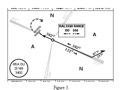
Most of this should be self-explanatory. For instance, the Identification box of the
Range Station lists the name of the range, the Identifier (DU), the frequency in
kilocycles (yeah, I’m using the old-style terminology – it just sounds better),
the A and N sectors, and the Identifier (DU) as heard in Morse code -.. ..-
You’ll also find a Minimum Safe Altitude published in a large circle somewhere here in the Plan Section. This altitude (3,400’ MSL on the KRDU chart) is the lowest altitude that one can blindly wander about and not strike cumulo-granite. There might be lower altitudes published and that’s okay because those routes, if flown accurately, will keep you away from terra-firma. However, if you don’t know where you are exactly, climb to the MSA at a minimum. Also note that this altitude is only good within 25 nautical miles of the station listed within the circle. The plan view also shows the location of the Range Station as a small circle, and all four of the Range Legs (along with their Magnetic bearings from the station). You might even notice that some of the Legs are hollow while some are filled. Those that are filled are used as part of the procedure, if ‘hollow’, they are not used on the approach or missed approach. The approaches also will consist of what is known as a Procedure Turn (PT). This is the ‘barbed arrow’ portion of the procedure (and sometimes there are other ways to accomplish the PT – but more later).
A little background: during an approach, one is rarely so perfectly aligned with the final approach course while Enroute as to allow him to just fly the final approach to the runway. That doesn’t even take into account that the pilot could not legally be low enough when approaching the Range to make a safe descent to the runway. Therefore, some form of PT will always be indicated on our approach plates and must always be flown. It includes protected airspace on either side, so you don’t have to do it perfectly, but you do have to give a good-faith attempt to remain on the course or track as it is depicted. In our KRDU example, no matter what direction from which you approach the Range, once you cross over, you will turn and fly outbound on the Southeast beam (which lies on the 122° mag bearing from the range) and after a certain amount of time, you’ll reverse your course by turning left to a heading of 077° for 30 seconds to a minute, then right to 257° until receiving the on course indication and return to the Range Station by flying inbound on the Southwest beam (a 302° bearing to the station). Now I mentioned a certain amount of time that the pilot must fly outbound before making the procedure turn. Technically this is not true. You may make the turn any time after the station as long as you stay within the published limits of the approach. This limit is located in the Profile View and will be discussed separately, but it is usually 10 nm from the station.
Flying range approaches is as much art as science -- there are literally as many ways to accomplish this as there are pilots, and a few techniques are described below.
After crossing the station (indicated by entering the cone of silence – no, not the one Maxwell Smart always wanted to use – an old US TV program I liked J), the final approach portion has begun and as anyone can see, flying the Northwest beam (302° bearing from the station), will eventually bring our intrepid aviator home. Again, techniques abound, one of them being the question of which side of the beam (or on the center) should the pilot fly? Use your head. If the runway were off to the right of the beam, I’d ride the right side. If it were off to the left, I’d probably use the other side. If the beam doesn’t go over the airport, I’d definitely use the side that lies closest to the airport. A careful study of the airport orientation and its relation to the beam will always pay off!
I told you earlier that there are some other ways to accomplish the PT, in other words approaches that have alternate forms of course reversal. One that comes immediately to mind is Roanoke, Virginia and is shown below:
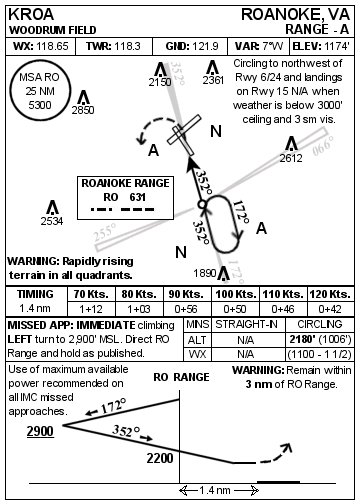
Figure 4.
This is one of the ‘busiest’ approach plates I created. And for one very good reason. The city of Roanoke, VA sits within a ‘bowl’ of mountains. Note the warning about ‘Rapidly rising terrain in all quadrants’. If you ever see that, you might want to concentrate just a little bit more on the approach. You can also see the distance limit for the approach within the Profile Section: ‘WARNING: Remain within 3 nm of RO Range’. And you can see how these constrained the design of the IAP. You don’t see a ‘barbed’ PT here. Instead, a simple holding pattern is flown in lieu of a procedure turn. Crossing the station one would turn and fly the holding pattern using one-minute legs (yeah, I know I didn’t specify that, but under 14,000 feet one minute legs are standard – trust me). Also note that this is a right-handed holding pattern. Right turns in holding are defined as standard holding patterns. (Guess which way the turns are in non-standard patterns.) That’s an important concept to remember, because, without specific ATC instructions to the contrary, the pilot is expected to hold with right turns. Oh yes, and within the holding pattern of course, the pilot would also be descending as indicated on the Profile View (again, more about that later – much more!)
There is at least one approach that makes use of a Procedure Track in lieu of a Procedure Turn. Here is one of that type:
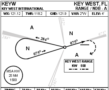
Figure 5.
Why was the Key West approach designed like this rather than with a simple PT? For two reasons – one, there are a bunch of towers on the West Leg of the KW Range which would have precluded as low an altitude as I wanted for the return to the Station after the PT and, secondly, because I wanted to include one of this type. Flying this is pretty self-explanatory. You’d fly out the West Leg of the Key West range (paying attention to remain within the designated maximum distance), make a left hand turn and intercept the 075° bearing into the range. (This is one of those RANGE/NDB approaches I talked about earlier.) Also, note that is a not a straight in – as designated by the ‘A’ in the approach name. Why, you ask? I’ll leave it to you to figure that one out – but here’s a hint – fly the approach in VMC (Visual Meteorological Conditions) and try to get down to the runway – then imagining doing it on Instruments.
Below is the Approach Data section of the KRDU Rwy 32 IAP:
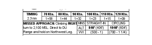
Figure 6.
It is divided into three sections: the Timing Section, the Missed Approach Instructions Section and the Minimums Section.
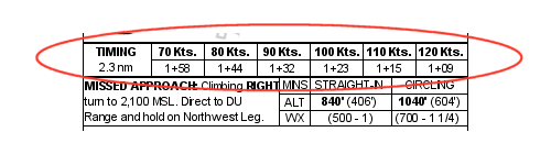
Figure 7.
The timing section is rather self-explanatory. The distance from the FAF to the MAP is precisely 2.3 nautical miles. At a given groundspeed the pilot can determine how long it will take to get to the MAP. If, at the expiration of this timing the airport has not been sighted, the pilot must pull up and execute the Missed Approach Instructions. Any delay, or for that matter, executing the missed approach instructions earlier than the expiration of timing, may result in your insurance company paying off on your Accidental Death and Dismemberment policy!
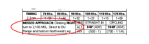
Figure 8.
Usually the first sentence in the Missed Approach instructions will indicate a climbing turn to a specified altitude. Sometimes, however, when obstructions are present, the requirement exists for a climb to a specified altitude before beginning a turn, or an immediate turn before even beginning a climb. If you follow the instructions precisely as they are written, you should be able to execute a safe Missed Approach.
After the initial turn and climb, follow on instructions are provided. Here the pilot is told to proceed directly to the DU Range and to hold on the Northwest Leg. One of the features I really wanted to include on these IAPs was a depiction of the Missed Approach Holding Pattern. However, there just wasn’t enough space to accommodate that. So fairly detailed instructions are provided instead. A few things might be left out however. For instance, this says to hold on the Northwest Leg. But can you picture that in your mind right now? I’ve basically left out anything that is ‘standard’. What is standard? Right turns in holding are always standard. Holding inbound when on course is always standard – in other words, when established in holding on the beam (or NDB bearing) you should be heading toward rather than away from the station. And bearing in mind that right turns are standard, you should make your outbound turn in holding to the right. Also, remember that one-minute legs are standard below 14,000 MSL. Adjust your timing on the outbound legs to more or less than one minute so that your inbound legs are exactly one minute from rollout of the turn to over the station.
HOLD ON FOR A MINUTE - we must now turn to that great thorn in the side of new instrument pilots (and some who are not so new) – the dreaded holding pattern entry method. There is no regulation stating that a pilot must use a particular method to enter holding. It is entirely technique. With that said, however, the pilot must stay within protected airspace – that airspace around the holding pattern within which terrain clearance is guaranteed at published holding altitudes. But protected airspace is only something that the geeks that design IAPs know about. The average pilot – and I’d venture to state that even most experienced pilots – don’t have the brain cells to remember all the minutia that would be nice to remember. Hard enough to remember flap speeds much less the radius of protection offered a Category C aircraft on the non-holding side of the pattern on Tuesdays in even-numbered months. Fugiddabowdit! (as my friends from Brooklyn, NY say).
So I’m going to give you a technique used by USAF pilots which complies with all of the airspace protections and regulations one could ever dream up. But first a couple of definitions – and as they say, a picture is worth a thousand words:
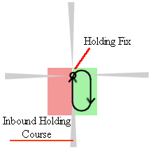
Figure 9.
And now for the easy rule, which is broken into 3 parts:
If your airplane’s heading is within 70° of the Inbound Holding Course, simply turn in the direction of holding onto the holding side and complete the hold.
If not within 70° then turn in the shortest direction to parallel the Holding Course. (This may put you on the non-holding side – which is okay.)
At any time, if you are conveniently aligned with the pattern you may execute a teardrop entry.
Let’s discuss each one in a little more detail (and some pictures) for clarification.
Situation #1: Your airplane is within 70° of the Inbound Holding Course (called the Direct Entry)
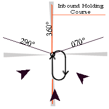
Figure 10.
Assume our inbound holding course is 360°. If your airplane heading is within 70° of 360° you may make a turn in the direction of holding (Called a DIRECT ENTRY). In this case, any of the three arrows depicting airplanes approaching the pattern would, upon reaching the station, execute a right turn (which is obviously the direction of holding) and enter the pattern – a direct entry. The rightmost airplane has more of a turn than the others, but will remain within protected airspace as long as a standard rate of turn is used.
Situation #2: Your airplane is not within 70° of the Inbound Holding Course (called the Parallel Entry)
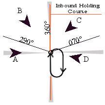
Figure 11.
Again, assume our Inbound Holding Course is 360°. Clearly, none of the arrows representing aircraft here are within 70° of our 360° Inbound Holding Course. So the pilots of all of these aircraft would resort to ‘turning in the shortest direction to parallel the Holding Course. Airplanes A and B would turn right (their shortest direction) to parallel the 180-360 line and Airplanes C and D would turn in their shortest direction - left.
That puts Airplanes A and B right where they’re supposed to be – on the holding side – they would simply complete the holding pattern as depicted. But Airplanes C and D will end up on the non-holding side with Airplane D being farther to the West than C simply due to the length of turn required. They would both turn left to a no-wind heading of 180 to parallel. Once established on the 180 heading, they would also have the option of ‘easing over’ to the holding course, i.e. move to the left a bit and head outbound on the Southern leg. Here’s the gotcha: Airplanes C and D must make a turn toward the holding side and join up with the holding pattern at the end of the standard one minute. This is depicted below:
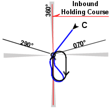
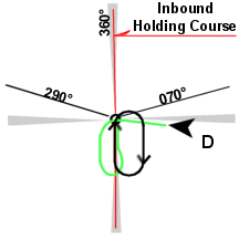
Figure 12a.
Figure 12b
Here, both Airplanes C and D have turned left to parallel the Holding Course. Airplane C has exercised his option of rejoining the holding course outbound (easing over), while Airplane D has not chosen this option. Note that both airplanes make their next turn toward the holding side (a left turn) and rejoin the pattern. Personally, were I the pilot of Airplane D, I would have eased over too, since I’m awfully near the edge of ‘protected’ airspace, but that’s just me.
Situation #3: Your airplane is conveniently aligned with the Inbound Holding Course (called the Teardrop Entry – optional)
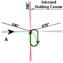
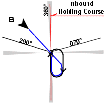
Figure 13a.
Figure 13b.
It seems pretty clear that Airplane B is conveniently aligned for the teardrop entry. All he has to do is continue straight ahead. A case can also be made that Airplane A is conveniently aligned as a relatively short right turn takes him into a teardrop position. Looking back at Figures 12a and 12b, not too many pilots would choose to perform a teardrop entry from C and none that are sane would do it from D. Simply put, it is pretty much left up to the individual pilot as to whether or not the airplane is conveniently aligned for a teardrop entry – and even if it is, a teardrop is not required.
So that’s it for holding entry. I used a bunch of pictures and a lot of words, but it really boils down to two options : Are you within 70 degrees or not? If ever in doubt, draw a little picture of your pattern and then draw your airplane’s relative position – it will all be real clear! I have drawn a picture for every holding pattern I’ve ever had to enter since 1979 and nobody has ever yelled at me.
3. Finally, we come to the Minimums Section.
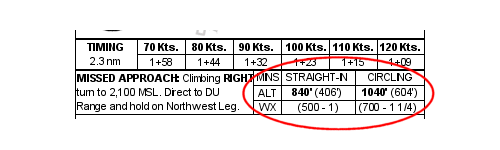
Figure 14.
This section tells you how low you may descend to during the Final Approach Portion. You will descend no lower than the altitude proscribed and may hold that altitude until the Missed Approach Point is reached. You may never descend below this altitude unless the Runway or the Airport Environment are in sight.
The table is basically two columns and two rows. The top-most row, labeled ALT depicts the MDA – Minimum Descent Altitude in feet above Sea Level and, in parentheses, the corresponding Height Above the Aerodrome in feet. The bottom row depicts the minimum weather reported by the station with which you may begin your approach. If the weather is reported below this ceiling (feet Above Ground Level) and/or visibility (in statute miles), you may not begin the approach (back in the 40s you could). Each row is, in turn, broken into two columns – one for Straight-In Approaches and one for Circling. One might ask “why even publish a Circling approach if a straight-in is available?” The answer is that you can’t always land on the straight-in runway. For example, using the KRDU approach, if the winds are out of the Southeast at 40 knots, the last thing you’d want to do is land on Runway 32. You might go off the end of the runway. In this case, you’d descend to 1040’ on your altimeter (the circling MDA) and hold that until the Airport environment is in sight. Then you’d begin a maneuver to bring your aircraft in line with whichever runway you determine is most advantageous. The prudent pilot would not descend below the circling minimum altitude until aligned with the runway. This isn’t always possible, but it’s a goal to shoot for. There is no procedure for which way to turn to execute the circle – the pilot must use his or her judgment and may circle in any manner desired as long as there is no note limiting a circle over a specified quadrant (e.g. Circling Prohibited Northeast of Runway 14/32.)
Bottom line: Don’t begin an approach when the weather is below the minimums. Don’t descend below the MDA (the boldface numbers). If you plan on circling use the circling MDA. If you fly a straight-in, break out, but can’t land (say a bus full of Nuns pulls out on the runway ahead of you), pull up to the circling MDA and circle for another try or to another runway – (the prudent pilot will have already planned for this contingency). Finally, if you must execute a missed approach from a circling maneuver ALWAYS make your initial turn toward the airfield, and join the published missed approach in the most expeditious manner. This is another gotcha that may cause your insurance company to pay an early benefit to your survivor.
Now a brain-teaser:
Look at the following IAP and tell me whether, if I’m flying this approach and I break out early and clearly see the runway, I may land straight ahead on Runway 5 or I must do a 360° circle and land…answer below.
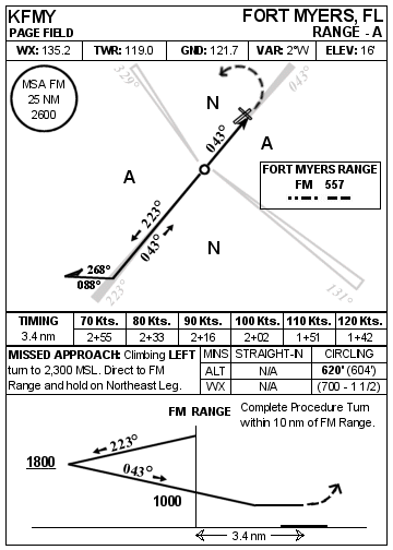
Figure 15.
Answer: (Scroll down)
V
V
V
V
V
V
V
V
V
V
V
V
You may land straight ahead. As there are no procedures as to how
to perform a circling approach, landing straight ahead is simply viewed as a
(very) simple circling maneuver. But realize that there is also a reason why
the approach designer did not include straight-in minima, and you’d better not
bend any metal or your license will be in jeopardy.
Section IV - Profile View
Here the pilot is presented with a ‘side’ view of the approach, which depicts, among other things, a stylized view of the approach, altitude limitations, courses, notes, and other miscellany.
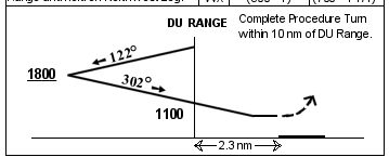
Figure 16.
First, note the turn limit of 10 nm in the upper right corner. Most approaches are limited to ten nautical miles. It is up to the pilot to ensure that the aircraft remains with in this limit at all times. You should also note the vertical line which projects up to the notation “DU RANGE”. This is an indication of the Final Approach Fix.
Now let’s discuss the lines and altitudes. You will note here that there is no altitude listed at the DU Range near the top of the section. This indicates that there is no mandatory altitude from which you must begin the procedure. It is up to the pilot to determine this altitude (within constraints of his ATC clearance, of course). Upon station passage and established outbound and on course (on the Southeast – 122° beam), the pilot may begin a descent to an altitude no lower than 1800 feet. The line under the ‘1800’ notation indicates that this is an ‘at or above’ altitude. An altitude with no line (such as the 1100 shown at the Final Approach fix) is a mandatory crossing altitude.
So, returning to our example, we are inbound to Raleigh after a long grueling flight from New York when we hear the following on our (imaginary) radio:
“ATC Clears Eastern 12 to the Raleigh Tower via standard Range Approach. Maintain 3000 feet until the Raleigh-Durham Range and contact the tower when over the range.”
We descend to 3000 feet and prepare for our approach. We note the PT altitude of 1800 and know that the aircraft is capable of such a descent. Upon station passage, we perform a little mnemonic I learned in the Air Force which you might want to incorporate into a little procedure you do every time you pass a station or fix: it is called “The five Ts”:
Time – start the
clock
Turn – Make the turn to intercept the desired course
Talk – Make a radio call (if required)
Track – Track your course
Throttles – Reduce power (if necessary) and begin descent
TIME - So we’ve reached the station, the first thing we do is start our clock. I usually figure 2 or 3 miles per minute and plan for a PT at the six mile point. 2.5 minutes seems to work awfully well for a DC-3.
TURN – Turn to intercept the course outbound.
TALK – Make your call to Raleigh Tower and let them know you are “Range Outbound”
TRACK – Make a course correction to nail the beam and, once established on the beam …
THROTTLES – Reduce power as necessary and begin a descent to 1800.
At the completion of our 2.5 minutes (using my technique), we make a left hand turn to 077° , clear our timer, and restart it. Shortly, the steady on course tone will change to twilight-A then a steady-A dit dah. We will follow this 077° heading for let’s say 30 seconds then begin a turn to 257°. Hopefully the airplane has slowed to about 110 – 120 now and during the turn, you may lower some flaps as necessary to aid your descent.
About now, you should be hearing the steady hum of the beam, so a turn to 302° and adjust for wind. Begin a descent to a mandatory 1100’ MSL. Perform preliminary landing checks and let the airplane begin to slow towards 90 knots or so. You will not want to begin the final approach portion at a speed much in excess of 90-95 knots, as it will be very difficult to slow down for landing.
Of course, you hear the steady hum of the on course (or twilight right if you prefer), and shortly the volume of the station begins to fade. Get ready for your FIVE Ts. I like to configure Gear and half flaps here, but that’s up to you. Upon entering the cone of silence, perform the Five Ts, and descend to your MDA. If at the completion of your timing, you do not have the Airport environment in sight, then pull up and execute the published missed approach procedure. If you do, you may either land on Runway 32 or (if you’re using circling MDA) circle to land on any runway.
I hope this has been of some use to you in explaining the hows and whys of our IAPs. If you have any questions at all, please feel free to send them to me – I can’t guarantee a quick answer, but I will guarantee an answer in time as long as you are a DC-3 Airways member (include your DCA ID# in the e-mail). If not, you need to join.
This project is truly a work in progress, and any one of you might have an idea that will make it better by quantum levels. I look forward to hearing from you – my e-mail is night56owl @ yahoo dot com. And yeah, I’m a little paranoid about putting my primary addy out there for all to see.
DISCLAIMER: WHILE THIS MAY SEEM STUPID: These copyrighted procedures are intended solely for the entertainment use of Flight Simulator Enthusiasts. They do not purport to conform to any parameters upon which modern approaches are based. Any use of them for any purpose other than computer flight simulation is expressly prohibited. Copies (paper or otherwise) may be made, but no changes to the procedures or data on the charts may be made or disseminated. Under no circumstances shall anyone use them for ‘real-world’ navigation, aerial or otherwise, and the user assumes complete and total liability in such use. I make no warrant against computer or computer accessory damage through use of these charts. But other than that, have fun! ;)